
- Install coolterm install#
- Install coolterm serial#
- Install coolterm drivers#
- Install coolterm driver#
- Install coolterm full#
Make sure to connect the power supply in correct polarity. Please refer to the marking on the board for more details.

If for any reason, an external 5V power supply needs to be used for the logic section of the module, the power select jumper should be configured properly before connecting the power supply. In most cases USB ports are capable of providing enough current for the module. So an external +5V power is not required unless USB port is unable to supply enough current.

By default the board is configured to use +5V supply from USB. This module uses +5V power supply to function properly. The table below summarizes the GPIO and Analog to Digital Converter input positions on the header. The internal Analog to Digital converter supports 10 bits resolution which is adequate for most applications. It is recommended to use a series resistor to protect the input from stray voltages and spikes. In contrast to GPIOs, Analog inputs can read voltages at any level between 0 to 3.3V.

A 470 Ohms series resistor is recommended for current limiting when connecting LED to a GPIO. So no additional circuitry is needed to drive regular LEDs. In output mode, GPIOs can source up to 8mA. It is recommended to use a series resistor with the GPIO/ADC pins when interfacing with other circuits. The ADC can acquire analog signal at the resolution of 10 bits per sample. All IO pins support 3.3V TTL signals and the ADC input range is 0 to +3.3V. Some of these pins can be used as Analog to Digital Converter inputs as well. In addition to the onboard relay, this module has 10 General Purpose IO pins that can be used for various custom applications. Also we have a large set of sample code to help you with)Īll aspects of the above steps are covered in the following sections including step by step demonstration. Optionally write a script or application to automate your task (More info on custom programming/scripting is available in this document.Enter commands (Very similar to entering commands at DOS prompt or Bash prompt).
Install coolterm serial#
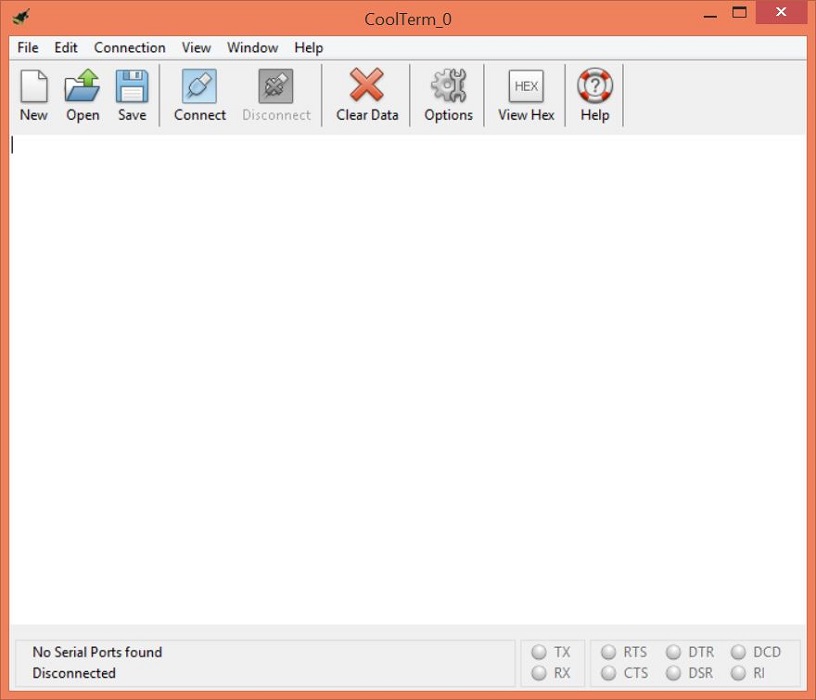
Open the COM port corresponding to the device using a Serial Terminal software.
Install coolterm driver#
Driver available for download on the product page.)
Install coolterm install#
Install coolterm full#
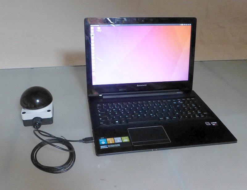
The module communicates with host PC over full speed USB link. This module also includes General Purpose I/Os, and analog inputs (multiplexed with GPIOs) that can be accessed over USB interface for extended functionality.
Install coolterm drivers#
This product has sixteen on board relays and associated drivers capable of controlling variety of devices including lamps, motors, locks etc… (Please see recommendations for using this product with inductive loads elsewhere in this document).


 0 kommentar(er)
